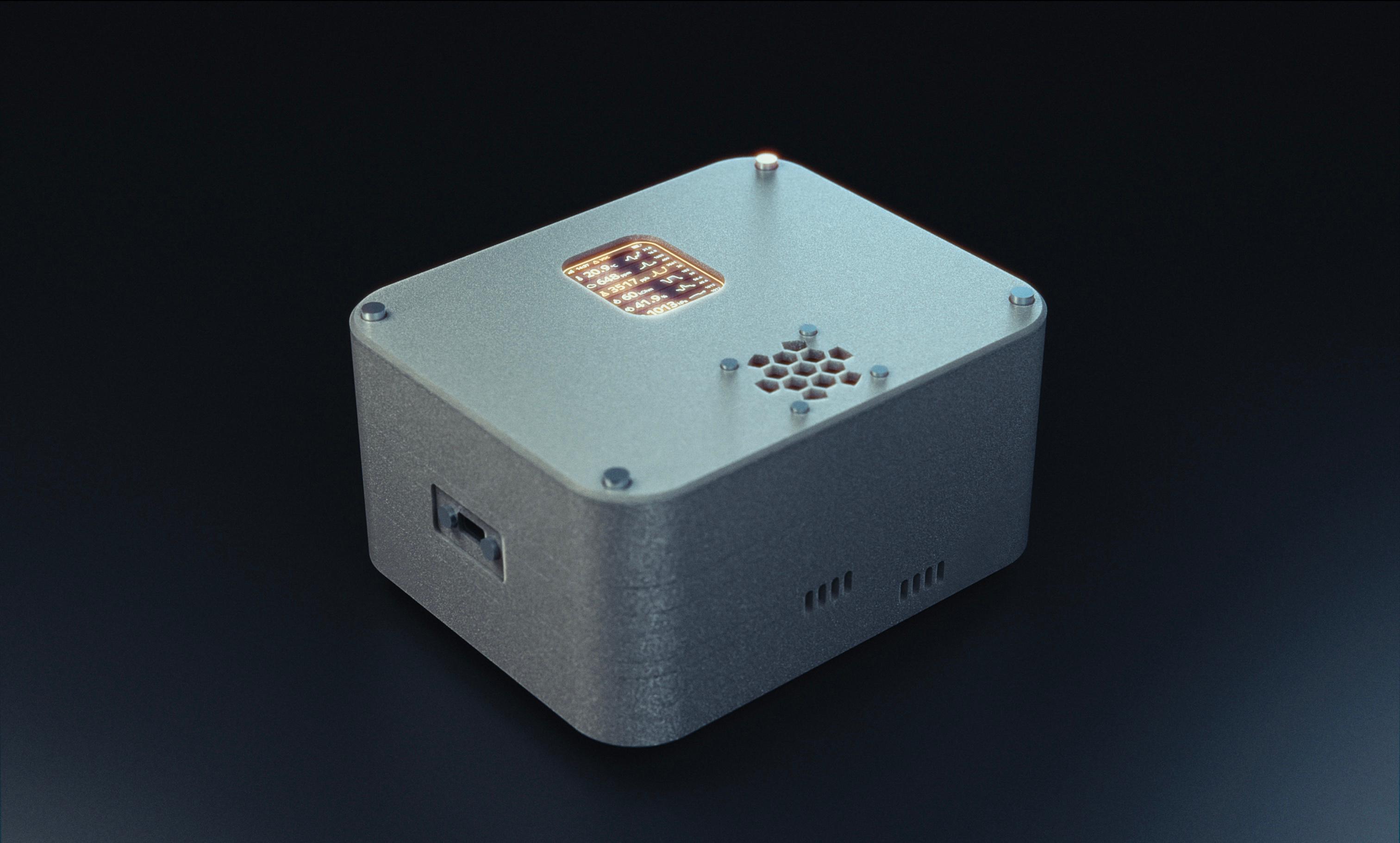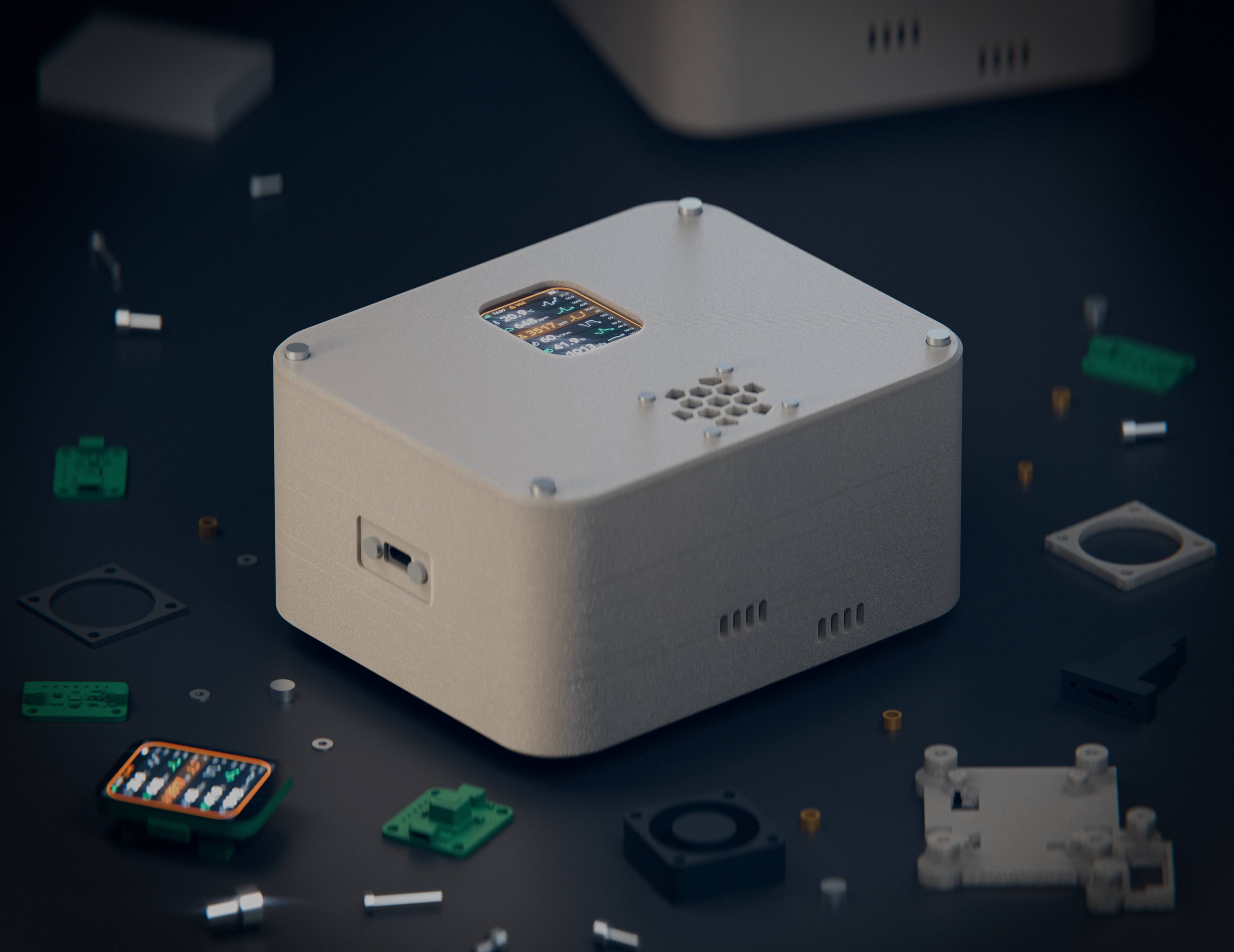
MICAMonitor for Indoor Climate & Air
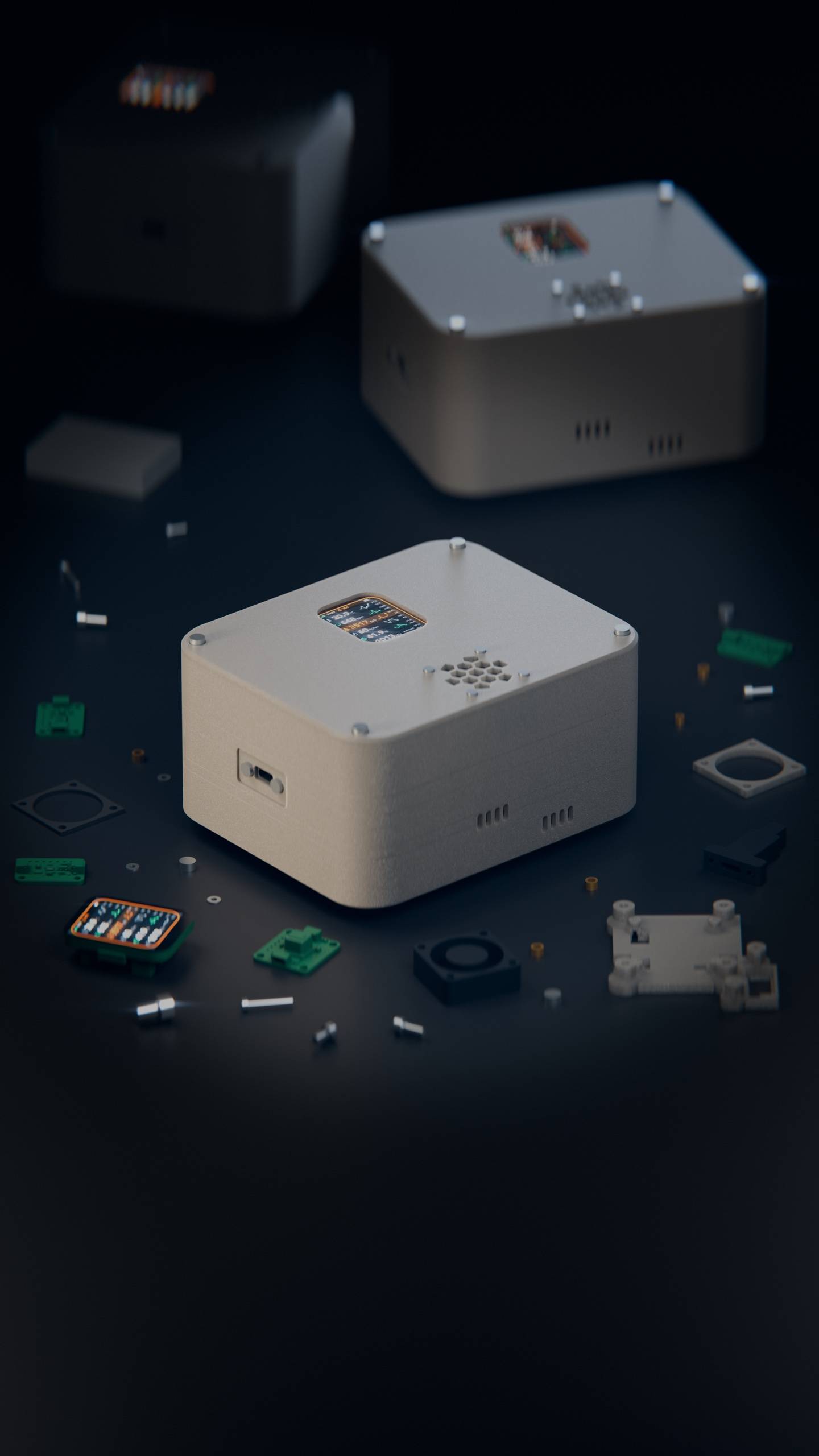
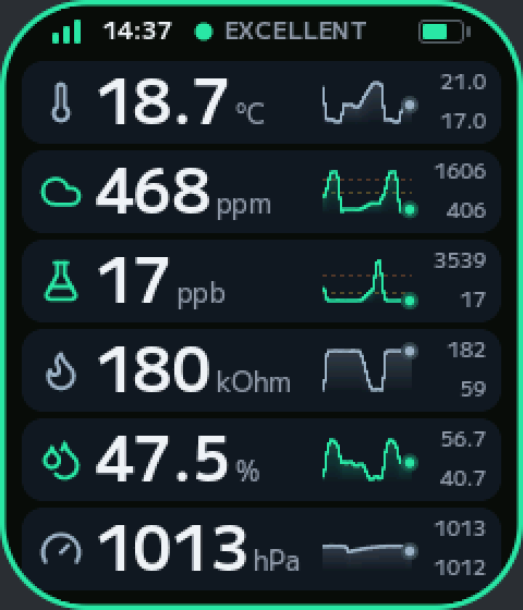
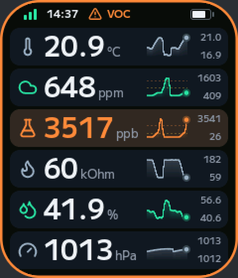
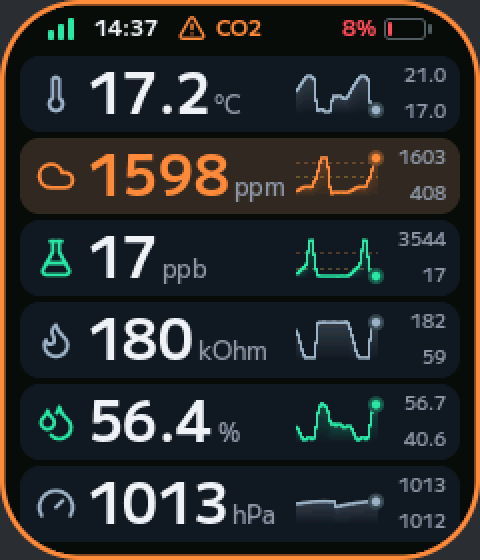
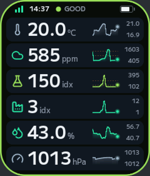
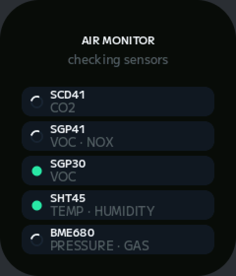
CO₂VOCtemperaturehumiditypressure on a friendly 1.69″ screen, and in Home Assistant over Zigbee. Built on the ESP32-C6, powered over USB-C or an optional LiPo, in a 3D-printable case with open-source firmware under the Apache 2.0 license.
Software
How to Flash
Build from source
Add the ESP32-C6 target and espflash:
rustup target add riscv32imac-unknown-none-elfcargo install espflash --lockedDownload the source code (Apache 2.0) and unzip it:
unzip air-monitor-0.1.1-source.zip && cd air-monitor-0.1.1Plug the board in, then build, flash and watch the log:
make run
Buttons
| Key | Click | Hold 2 s |
|---|---|---|
| BOOT | Wake | Fan test |
| PWR | Screen off | Power off |
Home Assistant, over Zigbee
| Sensors | Temperature, humidity, pressure, CO₂, VOC, battery |
| Fan | On, timed |
| Chime | Volume, repeat |
| Screen | Brightness, timeout |
| CO₂ calibration | Write the true CO₂ |
Assembly

Sensors
Cut one STEMMA QT cable and solder it to the board's header; chain the sensors in any order.
| Red | 3V3 |
| Black | G |
| Blue | SDA |
| Yellow | SCL |
Battery
It plugs into the board's BAT connector. Check the polarity first: many LiPo leads are wired the other way round for it.
Components
Everything to buy for one monitor, besides the printed parts.
| # | Part | Qty | Function | Source |
|---|---|---|---|---|
| Board and power | ||||
| 01 | Waveshare ESP32-C6-LCD-1.69 | 1 | MCU, 1.69″ screen, LiPo charger, buttons | Amazon |
| 02 | USB-C panel socket | 1 | Power and flashing through the body | Amazon |
| 03 | LiPo battery2000 mAh, 51.7 × 33.85 × 10.3 mm | 1 | Optional: runs it without USB | |
| 04 | STEMMA QT cable | 4 | Sensor chain; one is cut for the board | |
| SensorsAdafruit breakouts, chained over I²C | ||||
| 05 | SCD410x62 | 1 | CO₂ | Adafruit |
| 06 | SGP41 or SGP300x59 / 0x58 | 1 | VOC (SGP41: and NOx) | SGP41SGP30 |
| 07 | SHT450x44 | 1 | High Precision Temperature, Humidity | Adafruit |
| 08 | BME6800x77 | 1 | Pressure, gas | Adafruit |
| Fan driverOptional, soldered | ||||
| 09 | Fan30 × 30 × 10 mm, 5 V | 1 | Draws air past the sensors | |
| 10 | BC337NPN transistor, TO-92 | 1 | Switches the fan from the board's PWM | |
| 11 | STPS5H100BSchottky diode, DPAK | 1 | Absorbs the fan's turn-off spike | |
| 12 | Resistor330 Ω | 1 | Transistor base | |
| 13 | Electrolytic capacitor220–470 µF | 1 | Fan supply, close to the fan | |
| 14 | Ceramic capacitor100 nF–1 µF | 1 | Fan supply, close to the fan | |
| Hardware | ||||
| 15 | ScrewM2 × 6 | 19 | ||
| 16 | ScrewM2 × 10 | 4 | ||
| 17 | ScrewM2 × 16 | 4 | ||
| 18 | ScrewM3 × 6 | 4 | ||
| 19 | ScrewM3 × 8 | 4 | ||
| 20 | ScrewM5 × 8 | 2 | ||
| 21 | Heat-set insertM2 × 3, short | 23 | ||
| 22 | Heat-set insertM3 × 3, short | 8 | ||
| 23 | Heat-set insertM5 × 5.8, short | 2 | ||
| 24 | WasherM2, Ø5 / Ø2.2 × 0.5 | 13 | ||
| 25 | MagnetØ6 × 3 | 16 | ||
Fan Driver
Solder it yourself: a transistor lets the board's PWM switch the 5 V fan; a diode absorbs its turn-off spike.